he production of a new plastic Dehumidifier Dryer
Navigation: Technology>Latest Patent>Plastic Processing Application Technology
Manufacturing method of plastic dryer
The utility model relates to the technical field of plastic drying equipment, in particular to a plastic dryer.
Background technique:
At present, in order to improve the quality of plastic products, their raw materials are generally processed into plastic masterbatch. The loose plastic masterbatch is easily damp when exposed to the air. The chemical properties of plastic products made from damp plastic raw materials will be significantly reduced, which will affect the quality of the products. Therefore, loose plastic masterbatches need to be dried before being processed into plastic products.
For example, a plastic dryer is disclosed, including a drying box. The drying box is provided with two baffles and baffles. The two baffles form a funnel structure. One of the baffles can be rotated around the hinged edge and can be telescoped electrically. The rod is adjusted; the deflector is installed in the drying cylinder in an inclined and staggered manner. The lower end of the drying cylinder is connected with a hot air blower to inject hot air into the drying cylinder. The plastic masterbatch enters from the funnel, and then goes down along the deflector. Go up, so as to dry the plastic masterbatch.
The above-mentioned existing technical solutions have the following defects: when the plastic dryer is working, the internal temperature of the plastic dryer is relatively high, and there is dust, and the electric telescopic rod used to adjust the baffle needs to expand and contract when working, and it also needs power supply. And it is not reliable to use in high temperature environment.
Technical realization elements: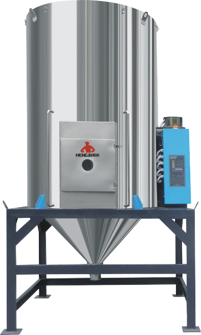
In view of the shortcomings of the prior art, the purpose of this utility model is to provide a plastic dryer, which has the advantage of being able to reliably control the flow rate of the plastic masterbatch into the drying oven, and to reliably control the plastic masterbatch on the deflector. The speed of movement.
The above-mentioned technical purpose of the present invention is achieved through the following technical solutions:
A plastic dryer includes a drying box and a deflector. The upper end of the drying box is provided with a feeding hopper, and the bottom end of the lower opening is provided with a movable plate. One side of the movable plate is hinged with a side of the lower opening, The other side of the plate is fixedly provided with movable rods, and both sides of the drying box are provided with adjusting holes. The movable rods penetrate through the adjusting holes. The adjusting holes are arc-shaped. The center of the adjusting holes is located on the rotation axis of the movable plate. There is a locking component, the upper end of the deflector is hinged to the inner wall of the drying box, the lower end of the deflector is connected with a traction rope, the traction rope runs through the side wall of the drying oven, and a buckle assembly for fixing the traction rope is arranged outside the side wall.
By adopting the above technical solution, before the plastic dryer works, according to the degree of moisture of the plastic masterbatch, the worker unlocks the movable rod. Because the adjusting hole is arc-shaped, and the center of the arc-shaped adjusting hole is located on the axis of rotation of the movable plate, it is movable The rod can adjust the movable plate along the adjustment hole, thereby changing the opening size of the lower opening of the hopper. After determining the size, lock the movable lever. Then the position of the traction rope can be adjusted, and the traction rope can be connected to the buckle assembly, thereby changing the angle between the baffle plate and the inner side wall of the drying box. By manually adjusting the movable plate and the traction rope, we can more reliably control the flow rate of the plastic masterbatch into the drying box, and also more reliably control the speed of the plastic masterbatch movement on the deflector.
The utility model is further arranged as follows: the locking assembly includes a wing nut and a spring washer, the wing nut is threadedly connected to the end of the movable rod, the spring washer is sleeved on the movable rod, and the spring washer is located between the wing nut and the outer side wall of the drying box between.
By adopting the above technical solution, the nut is selected as a wing nut, so that the staff can directly twist the nut by hand, which is more convenient and quick when adjusting the movable plate; because the plastic dryer will produce vibration when working, the tightened wing nut It may loosen slowly. A spring washer is set between the wing nut and the outer wall of the drying box to effectively prevent the fixing nut from loosening.
The utility model is further configured as follows: the movable rod is covered with a baffle, the baffle is in an arc shape, the baffle is located between the spring washer and the outer side wall of the drying box, the baffle is concentric with the adjusting hole, and the outer wall of the drying box is provided with a sliding groove. The chute is arc-shaped, the chute is concentric with the adjusting hole, and the depth of the chute is the same as the thickness of the baffle.
By adopting the above technical solution, because the adjusting hole is located at the bottom of the arc-shaped chute, the central angle of the chute is greater than the central angle of the stop plate, and the central angle of the chute is greater than the central angle of the adjusting hole. The two sides of the stop plate and the two sides of the chute The wall conflicts, and the baffle and the slide groove and the adjustment hole are all at the same center, so the baffle can cover the adjustment hole at any position, thereby effectively preventing the plastic masterbatch and dust in the drying box from leaking; making the appearance of the plastic dryer Beautiful, it also protects and limits the baffle.
The utility model is further configured as follows: the central angle of the adjusting hole is 45 degrees.
By adopting the above technical solution, the central angle of the adjustment hole is 45 degrees, which further limits the adjustment range of the movable plate and prevents the movable plate from being adjusted too much.
The utility model is further arranged as follows: a sealing sleeve is provided where the traction rope passes through the side wall of the drying box, and the traction rope passes through the sealing sleeve.
By adopting the above technical solution, a sealing sleeve is arranged at the side wall of the drying box through the traction rope, so that when the plastic dryer is working, the plastic masterbatch and dust in the drying box are effectively prevented from leaking.
The utility model is further configured as follows: a pulley block is symmetrically arranged inside and outside the side wall of the drying box, the pulley block includes an inner pulley and an outer pulley, the pulley block is fixed on the side wall of the drying box by bolts, the traction rope is wound around the pulley block, between the inner pulley and the outer pulley The towing rope is kept level.
By adopting the above technical solution, a pulley block is symmetrically arranged inside and outside the side wall of the drying box, and the traction rope conflicts with the top of the pulley block. The pulley block can support the traction rope to move in the sealing sleeve. When the traction rope always moves on the horizontal line, the sealing sleeve is effectively improved. Service life.
The utility model is further configured as follows: the buckle assembly includes a groove and a fixing hook, the groove is vertically arranged on the outer side wall of the drying box, the groove is located under the pulley block, and a row of fixed hooks is vertically arranged in the groove. Towards the bottom of the drying box, the number of fixing hooks is four.
By adopting the above technical solution, the fixing hook is arranged in the groove to facilitate transportation and prevent the fixing hook from hooking other things and interfering with the work; the four fixing hooks provided make it convenient to adjust the inclination angle of the deflector.
The utility model is further configured as follows: the head of the traction rope is provided with a hand-held part, and a fixedly connected buckle is provided near the head.
By adopting the above technical solution, the head of the traction rope is provided with a hand-held part, which is convenient for the staff to hold the traction rope, so that the traction rope can be pulled better; the buckle is fixed and connected at a position close to the head, and when adjusted by the traction rope When the deflector is used, the buckle is fastened to the fixing hook, so that the adjustment is more convenient and faster.
To sum up, the beneficial effects of the present invention are: before the plastic dryer works, according to the degree of moisture of the plastic masterbatch, the worker unlocks the movable rod, because the adjustment hole is arc-shaped, and the center of the arc-shaped adjustment hole is located on the movable plate The movable rod can adjust the movable plate along the adjustment hole, thereby changing the opening size of the lower opening of the hopper. After determining the size, lock the movable lever. Then the position of the traction rope can be adjusted, and the traction rope can be connected to the buckle assembly, thereby changing the angle between the baffle plate and the inner side wall of the drying box. By manually adjusting the movable plate and the traction rope, we can more reliably control the flow rate of the plastic masterbatch into the drying box, and also more reliably control the speed of the plastic masterbatch movement on the deflector.
Description of the drawings
Figure 1 is a schematic diagram of the three-dimensional structure of a plastic dryer in an embodiment of the present invention;
Reference signs: 1. Drying box; 10, cover; 11, buckle; 12, bin window; 13, feed hopper; 131, lower opening; 14, discharge port; 15, movable plate; 151, movable rod 152, wing nut; 153, baffle; 154, adjusting hole; 155, chute; 156, spring washer; 16, deflector; 17, connecting ring; 18, traction rope; 181, sealing sleeve; 182, Handle; 183, buckle; 19, groove; 191, fixed hook; 110, pulley block; 111, inner pulley; 112, outer pulley; 2. hot air device; 21, hot air blower; 22, air duct; 3. support.
detailed description
The utility model will be further described in detail below in conjunction with the drawings.
1 and 2, a plastic dryer includes a drying box 1 and a bracket 3. The drying box 1 is a rectangular box body, the drying box 1 is fixedly connected to the bracket 3, and a hot air device 2 is provided on one side of the drying box 1. The device 2 is connected to the lower end of the drying box 1, and the hot air device 2 includes a hot air blower 21 and an air pipe 22, and the air pipe 22 communicates the hot air blower 21 and the drying box 1.
2 and 4, the top of the drying box 1 is provided with a lid 10, and the bottom end of the drying box 1 is provided with a discharge port 14. One side of the lid 10 is hinged on the side of the drying box 1, and the lid 10 is opposite to the hinged one. A buckle 11 is arranged on the side. The buckle 11 allows the lid 10 to be tightly closed on the drying box 1 and at the same time facilitates the opening and closing of the lid 10. The side wall of the drying box 1 is provided with a bin window 12 for observing the inside of the drying box 1.
3, a feeding hopper 13 is provided on the top of the drying box 1. The feeding hopper 13 is in the shape of a funnel, and the lower opening 131 of the feeding hopper 13 is biased toward one of the side walls of the drying box 1. A movable plate 15 is provided at the bottom end of the lower opening 131, one side of the movable plate 15 is hinged to a side of the lower opening 131, the hinged side of the movable plate 15 and the lower opening 131 is close to the middle of the drying box 1, and the other side of the movable plate 15 is fixed A movable rod 151 is provided, and the movable plate 15 can be attached to the lower opening 131 to close the lower opening 131.
4 and 5, the drying box 1 is provided with adjustment holes 154 on both sides, the movable rod 151 is inserted in the adjustment hole 154, the adjustment hole 154 is arc-shaped, and the center of the adjustment hole 154 is located on the rotation axis of the movable plate 15. The central angle of the adjusting hole 154 is 45 degrees; the outer wall of the drying box 1 is provided with a sliding groove 155, which is arc-shaped, and the sliding groove 155 is concentric with the adjusting hole 154. The adjusting hole 154 is located at the bottom of the sliding groove 155, and the center of the sliding groove 155 is The angle is greater than the central angle of the adjusting hole 154; the movable rod 151 is covered with a baffle 153, which is arc-shaped, and the baffle 153 is slidably arranged in the sliding groove 155, and the two sides of the blocking plate 153 and the sliding groove 155 The side walls conflict; the end of the movable rod 151 is threadedly connected with a wing nut 152, a spring washer 156 is arranged between the wing nut 152 and the stop piece 153, and the spring washer 156 abuts against the outer wall of the drying box 1; the stop piece 153 is designed for When the movable rod 151 slides to any position in the adjusting hole 154, the blocking piece 153 can cover the adjusting hole 154.
3 and 6, the upper end of the baffle plate 16 is hinged to the inner wall of the drying box 1, the number of baffle plates 16 is two, the baffle plate 16 is up and down, and the two baffle plates 16 are hinged on the two opposite sides. On the side wall. There is an angle between the baffle 16 and the inner side wall of the drying box 1. A connecting ring 17 is provided in the middle of the lower end of the baffle 16, and the connecting ring 17 is fixedly connected with a traction rope 18, which penetrates the side wall of the drying oven 1, and the head of the traction rope 18 outside the drying oven 1 is provided with a handle 182, which is close to A clasp 183 is provided at the handle 182. The side wall of the drying box 1 is provided with a sealing sleeve 181, and the traction rope 18 is passed through the sealing sleeve 181. A pulley block 110 is symmetrically arranged inside and outside of the side wall of the drying box 1. The pulley block 110 includes an inner pulley 111 and an outer pulley 112. The pulley block 110 is fixed to the side wall of the drying box 1 by bolts. When the traction rope 18 moves in the sealing sleeve 181, the traction rope 18 always keeps moving on a horizontal line.
3 and 7, a rectangular groove 19 is provided on the outer side wall of the drying box 1, and the groove 19 is located directly under the pulley block 110. A row of fixed hooks 191 is vertically arranged in the groove 19, and the fixed hooks 191 face downwards. The number of fixed hooks 191 is four. From top to bottom, the angle between the deflector 16 and the side wall of the drying box 1 is 45 degrees, 50 degrees, 55 degrees and 60 degrees. The fixing hook 191 is used to buckle the buckle 183.
The implementation principle and beneficial effects of this embodiment are:
Before the plastic dryer works, according to the degree of humidity of the plastic masterbatch, the worker loosens the wing nut 152, and the movable rod 151 can adjust the movable plate 15 along the adjustment hole 154, thereby changing the opening size of the lower opening 131 of the hopper 13. During the adjustment process, the baffle moves in the sliding groove 155. When the baffle 153 slides to any position, the baffle 153 can cover the adjustment hole 154. The wetter the plastic masterbatch is, the smaller the opening size of the lower opening 131 is, and the smaller the feed flow rate; otherwise, the larger. After determining the size, tighten the wing nut 152. Then pull the traction rope 18 to adjust the position of the buckle ring 183. The buckle ring 183 is sleeved on a suitable fixing hook 191 to change the angle between the deflector 16 and the inner side wall of the drying oven 1. The wetter the plastic masterbatch, the buckle ring 183 The lower the fixed hook 191 is sleeved, the larger the angle, the smaller the inclination of the deflector 16 and the slower the movement speed of the plastic masterbatch on the deflector 16; otherwise, the higher it goes. Then the hot air blower 21 is started, and the hot air flows into the drying box 1 from the lower end of the drying box 1 through the air duct 22. The plastic masterbatch enters from the hopper 13 and then falls on the deflector 16 to move. During the movement, the plastic masterbatch Heated by the hot air, the finally dried plastic masterbatch is discharged from the discharge port 14.
In summary, by manually adjusting the movable plate 15 and the traction rope 18, we can reliably control the flow rate of the plastic masterbatch into the drying oven 1, and also reliably control the speed of the plastic masterbatch on the deflector 16.
The examples of this specific embodiment are all preferred examples of the utility model, and the scope of protection of the utility model is not limited accordingly. Therefore: all equivalent changes made in accordance with the structure, shape, and principle of the utility model are all Should be covered within the scope of protection of the utility model.
|


 163.com